
The Disk2FDI cable consists of a 2-wire cable, about 50 cm (2 feet) long, making a connection between pin 30 (Read-Data) of the floppy cable, and pin 10 (ACK or Acknowledge) of the parallel port (also called printer port or LPT port) connector, as well as a connection between pin 8 (Index) of the floppy cable, and pin 13 (SLCT, Select or Printer On-line) of the parallel port connector.
Here, we assume that the cable is soldered on one end to a connector that will attach to the floppy cable, this connector being a standard 3.5" floppy 34-pin male connector, and to the other end to a connector that will plug into the parallel port, this connector being a standard DB-25 (also called Sub-D 25) male connector.
The diagram below represents how the correct pins from the floppy cable and the parallel port are connected together by a Disk2FDI cable.

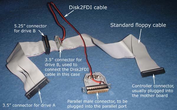
Picture 1 below shows the final cable connected to a standard floppy cable.
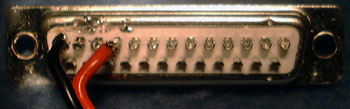
Picture 2 below shows the back side (soldering side) of the DB-25 connector, to be plugged into the parallel port.
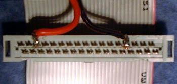
Picture 3 below shows the floppy connector plugged onto the floppy cable.
Picture 4 below shows the front side (plug side) of the floppy connector, to be plugged onto the floppy cable, as shown in pictures 1 and 3 above.
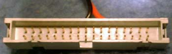
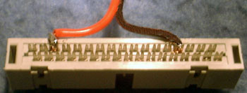
Picture 5 below shows the back side (soldering side) of the floppy connector.
This page © 2004 Vincent & Sonia Joguin